Description
This widely used sensor, the HC-SR04-Ultrasonic Range Finder, is used in many applications where it is necessary to measure distance and find objects.
The ultrasonic transmitter and receiver are formed by two projects that resemble eyeballs on the front of the module. Like bats or dolphins, the HC-SR04 ultrasonic sensor utilizes sonar to calculate the distance to an item.
In one compact package, this ultrasonic sensor module functions as a transmitter, receiver, and control circuit. It is made of a highly practical and little design. It comes in easy-to-use packaging and provides high-range accuracy and consistent readings. Unlike Sharp rangefinders, its operation is unaffected by sunshine or dark materials (although acoustically soft materials like cloth can be difficult to detect).
As this module's I/O pins, the Trigger and Echo pins may be linked to the I/O pins of the microcontroller or Arduino. The Echo pin rises high for a predetermined period, which will be equivalent to the time it takes for the wave to come back to the sensor when the receiver detects the return wave.
The HC-SR04 Ultrasonic Ranging Module offers non-contact distance sensing capabilities between 2 and 400 cm with a 3 mm range precision.
Features
- provides a broad range of measurements from 2 cm to 400 cm.
- consistent performance
- accurate measurement of distance
- High-density
- little blind space
Specifications
- Input Voltage: 5V
- Current Draw: 20mA (Max)
- Digital Output: 5V
- Digital Output: 0V (Low)
- Working Temperature: -15°C to 70°C
- Sensing Angle: 30° Cone
- The angle of Effect: 15° Cone
- Ultrasonic Frequency: 40kHz
- Range: 2cm - 400cm
- Dimensions
- Length: 43mm
- Width: 20mm
- Height (with transmitters): 15mm
- Center screw hole distance: 40mm x 15mm
- Screw hole diameter: 1mm (M1)
- Transmitter diameter: 8mm
PinOuts
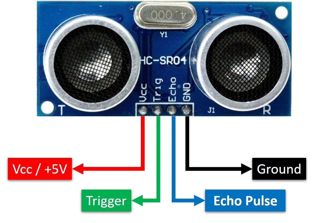
VCC: gives the HC-SR04 ultrasonic sensor power. It may be connected to your Arduino's 5V output.
Trig: To start ultrasonic sound pulses, a pin is utilized. The sensor starts an ultrasonic burst by holding this pin HIGH for 10 s.
Echo: When an ultrasonic burst is a broadcast, the pin rises high. It stays high until the sensor gets an echo, at which point it becomes low. The distance may be determined by counting the number of seconds the Echo pin remains up.
GND: The ground pin is. Attach it to the Arduino's ground.
Layout
Working
The HCSR04 timing diagram is displayed. Trig of SR04 has to receive a high pulse (5V) for at least 10us before measurement can begin. Once this happens, the sensor will begin sending out 8 cycles of ultrasonic bursts at 40kHz and waiting for the reflected bursts. The sensor will set the Echo pin to high (5V) and delay for a length of time (width) proportional to distance when it detects ultrasonic from the receiver. Measure the breadth (Ton) of the Echo pin to determine the distance.
Time = Width of Echo pulse, in uS (micro second)
- Distance in centimeters = Time / 58
- Distance in inches = Time / 148
- Or you can use the speed of sound, which is 340m/s
Application
- Loop control
- Roll diameter, tension control, winding and unwind
- Liquid level control
- Thru beam detection for high-speed counting
- Full detection
- Thread or wire break detection
- Robotic sensing
- Stacking height control
- 45° Deflection; inkwell level detection; hard to get at places
- People detected for counting
- Contouring or profiling using ultrasonic systems
- Vehicle detection for car wash and automotive assembly
- Irregular parts detection for hoppers and feeder bowls
- Presence detection
- Box sorting using a multi-transducer ultrasonic monitoring system


